

Programming ESP8266
The ESP8266 is a cheap WiFi enabled module that can be used very easily for simple and complex projects. Here I want to write my experience with the device, for reference and perhaps help others
Environment Setup
There are many sites and videos that detail how to install the platform and the various tools for Arduino. The Xtensa processor (the one used in this module and the ESP32 series) has a GCC compiler that is used by the Arduino environment and in here I intend to use it directly.
The following files I downloaded:
esptool-0.4.13-linux64.tar.gz(https://github.com/igrr/esptool-ck)linux64-xtensa-lx106-elf-gb404fb9.tar.gz(https://github.com/esp8266/Arduino/releases/download/2.3.0/linux64-xtensa-lx106-elf-gb404fb9.tgz)mkspiffs-0.2.0-no_magic_length-linux64.tar.gz(https://github.com/igrr/mkspiffs)
The first is a set of tools that is used to download your new firmware to the device. The second is the GCC compiler for the Xtensa LX106. They are all downloaded by the Arduino IDE so if it is installed they are likely already present on your system.
To test that eveything is working as it should, use esptool to download
the AIThinker AT firmware to the ESP8266 device. Firmware is available here.
Before powering the device you must put it into programming mode, this can
be achieved by connecting GPIO_0 to GROUND then power-cycle the device.
./esptool -cp /dev/ttyUSB0 -cb 115200 -cf ~/esp8266/ai-thinker-v1.1.1.bin
You can also try the esptool.py command (see references).
./esptool.py -p /dev/ttyUSB0 write_flash 0x00000000 ~/esp8266/ai-thinker-v1.1.1.bin
Once written, reset the device, open a serial terminal and verify it worked, here are some commands to try, they should all solicit some response from the device:
ATZ
AT+CWMODE=3
AT+CWLAP
AT+GMR
AT+RST
Sample Programme
First configure and check the toolchain is working:
export PATH=$PATH:~/esp8266/xtensa-lx106-elf/bin
xtensa-lx106-elf-gcc --version
xtensa-lx106-elf-gcc (crosstool-NG 1.20.0) 4.8.2
The sample programme I will use is available from the expressif github page: https://github.com/espressif/ESP8266RTOSSDK. Clone this repo and play along with me :-).
The Makefiles in the ESP8266_RTOS_SDK use an environment variable that
must be set first.
export IDF_PATH=~/esp8266/ESP8266_RTOS_SDK
Open the ESP8266_RTOS_SDK/examples/wifi/wps directory and run
make menuconfig. Leave everything alone except the Serial flasher config
(we will not use it but it will output all the arguments for esptool.py which is nice).
In the build/ directory there should be our compiled code wps_example.bin
along with a number of directories containing object files. There will also
be warnings during compilation... we may have to resolve these later. Now,
write the binary code to the device:
GPIO_0toGND- read the
esptool.pycommand as outputted by the make or justmake flash - Remove the
GPIO_0toGNDlink and ower-cycle the device - I would suggest minicom but it does not support the 74880 baud rate that is enabled in the firmware of the ESP8266
- so... use
idf_monitor.py:tools/idf_monitor.py examples/wifi/wps/build/wps_example.elf
When connected there should be occasional output of:
scan status 2
wps scan
build public key start
build public key finish
wifi_wps_scan : 17
scan status 4
Also... boot messages... but idf_monitor seems to die when they appear.
Pins
The ESP8266 mini module with a 0.1 inch header for UART and power is the cheapest and simplest device.
+-----------------+  View from TOP (
|                 |
| [2] [4] [6] [8] |  1 - RX
|                 |  2 - VCC
| [1] [3] [5] [7] |  3 - GPIO_0
|                 |  4 - RST
|                 |  5 - GPIO_2
|   ICs Here      |  6 - CH_PD
|                 |  7 - GND
|                 |  8 - TX
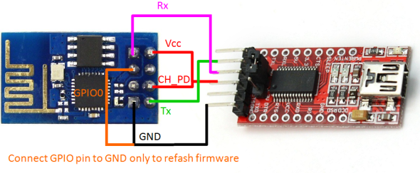
This is not my artwork... if it is yours and you would like a link please send me an email.
References
- Python esptool (esptool.py)
- Alternative esptool.py from expressif
- https://github.com/pfalcon/esp-open-sdk
- Introduciton using the ESP open SDK
- https://gist.github.com/sentinelt/3f1a984533556cf890d9 setting non-standard baud rate (74880 as seen earlier)
- https://stackoverflow.com/questions/12646324/how-to-set-a-custom-baud-rate-on-linux more on the baud rate thing
- NTP Client Example (Arduino)
- Arduino Makefile
- Hackaday - Makefile writeup
- DS18B20 for ESP8266
- Instructables on ESP8266
- WS2812 I2S Stuff
- Real Bare Metal Work on ESP8266