

I2 C with the Raspberry Pi
Note: Full source (still not finished) is available github.com/drcrane/raspberryrfid.
The Raspberry Pi has a few different interfaces available to it, one is I2C (a protocol created by Philips and used in many places, it is the basis of VESA DDC!). I had the opportunity recently to interface with an SL030 RFID Mifare reader, it is a nifty little thing that is quite cheap from SK Pang Electronics. The SL030 is based on an NXP 80C51 microcontroller (P89LPC922) and a specialised IC the MFRC522, also of NXP semiconductor origin.
This will be much clearer if you have a basic understanding of electronics and I2C, and if you have read the Broadcom datasheet page 34 (see References section below).
Hardware
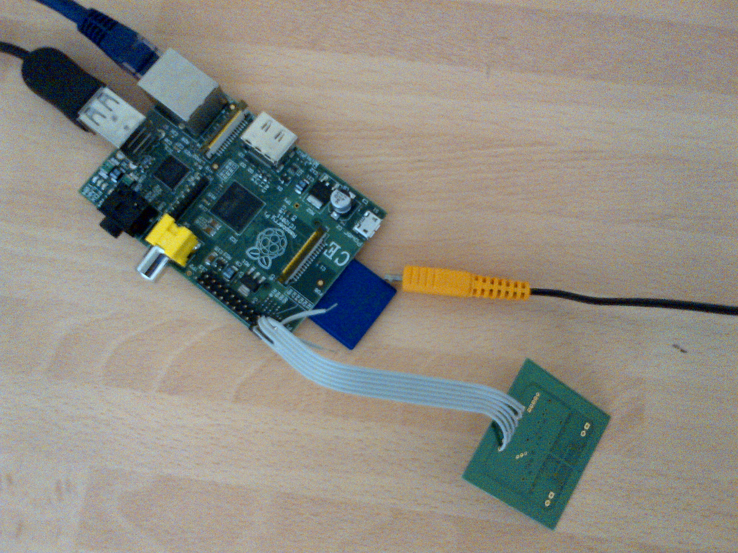
This is pretty simple so I won't spend too long on it... I got to draw and take a picture ;-).
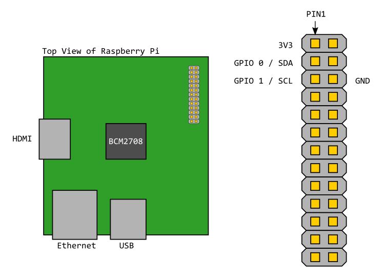
One thing to note (if you look in the source code for the driver) the GPIO ports are configured for you and by default (as with most microcontrollers) are inputs. These are pulled high already (as per the I2C specification) with 1K8 pullup resistors. All this means the only thing you need to do is connect up the SL030 by matching up the letters on the pins ;-).
Kernel Compile and Install
As many people have a tutorial on this I will not bother to recreate it, I just wish to thank Chris Boot, selsinork and everybody who contributes to eLinux.
# Stuff here to help my poor struggling brain
crossdev -S -v -t armv6j-hardfloat-linux-gnueabi
git clone --depth 1 git://github.com/selsinork/linux.git
# from kernel directory
cp arch/arm/configs/bcmrpi_cutdown_defconfig .config
make ARCH=arm CROSS_COMPILE=armv6j-hardfloat-linux-gnueabi- oldconfig
make ARCH=arm modules_install INSTALL_MOD_PATH=/tmp/modules
Incase it was not obvious I used selsinork's kernel ;-)
Talking to SL030 via I2C
Once the Kernel was compiled I had my circuit all set up and wrote a nice bit of C and tried to get the firmware version number from the device. It should be:
0b f0 00 53 4c 30 33 30 2d 33 2e 32
According to the datasheet... what I got was not that, the first byte seemed to be fine but all subsequent bytes had the MSB set so I kept getting this:
0b f0 80 d3 cc b0 b3 b0 ad b3 ae b5
Too coincidental to be rubbish coming back from the device, the only thing I could think was that the Raspberry Pi clock was too fast... but then why are all the other bits of each byte correct? The Pi also says that it is running at 100KHz which is well within the tolerance of the SL030 which says 0-400KHz.
After trying to find the Broadcom datasheets and discovering that
"Broadcom are not like STMicro or Philips" which meant no datasheet for
me :-( anyway, without an Oscilloscope (which I am ashamed to say I do
not own) and no idea of what registers to fiddle with I thought oh, this
is going to be a long slog with the existing code. Fortunately for me
Eben and co. managed to get Broadcom to release the details required and
so I have been able to track down the problem to the DEL
register... more specifically the REDL bits which determine
how long the MCU should wait after SCL changes from
LO to HI. DEL is not modified by
the current I2C Bus implementation and so the Raspberry Pi is just using
the reset value of 0x30. This is too quick for the IC on
the SL030 to pull the SDA line LO so the first
bit is sampled when it is HI.
My Change to the I2C Bus Driver
The datasheet says that by default the hardware will wait 0x30 core cycles, if the core frequency is nominally 150MHz that would be 320 nanoseconds. Our core is running faster than that and 0x30 evaluates to 192ns. I did try to change the REDL value to 0x50 which with a CDIV of 0x9c4 should have given 320ns, that did not work.
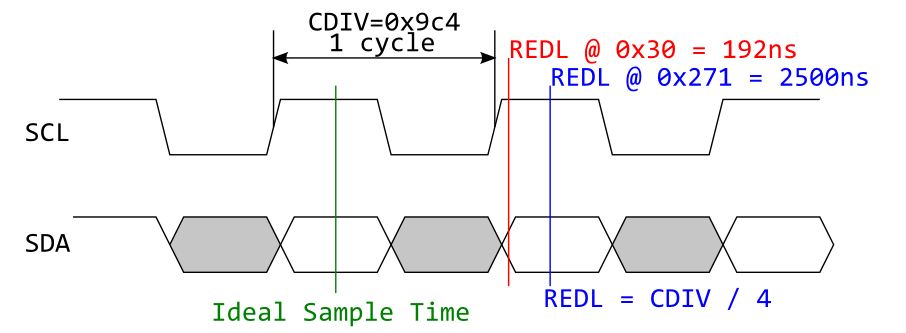
This is not quite how the I2C specification expects the bus to
work however the specification says that SDA should be
stable for the whole time SCL is high. Normal I2C
implementations sample very close to the rising edge (as is the default
configuration for the BCM2835) it is expected that the SDA
line will be set correctly in the preceeding low half clock (grey on my
diagram). For the SL030 the SDA line is not driven low
until later so the first bit of each byte, after the first byte, are
read as 1. So, the Ideal Sample Time here is only
the ideal sample time for the SL030 but should work with other
peripherals.
Please see my patch to selsinork's kernel.
References
- eLinux - Kernel Compilation
- http://www.jtek.cz/?p=62
- http://www.coridiumcorp.com/cHELP/scr/HwI2c.htm
Find out about I2C (simple introduction) - ics.nxp.com/support/documents/interface/pdf/an10216.pdf
AN10216-01 the I2C Manual (Local Copy) - Broadcom BCM2835 ARM Peripherals Manual (Local Copy)